

Approx. Straight-line Linkages - Educational Model


Approx. Straight-line Linkages - Educational Model
- Made to order — 3D printed after you buy
- Free shipping on orders over $25
- Quality checked before it ships
- Questions? Contact us · Returns
My Educational Mechanical Examples Series
This model is one of my educational mechanical mechanism examples on 80mm x 80mm base plates.
You can find all models of the series in this collection => [Mechanical Mechanism Examples]
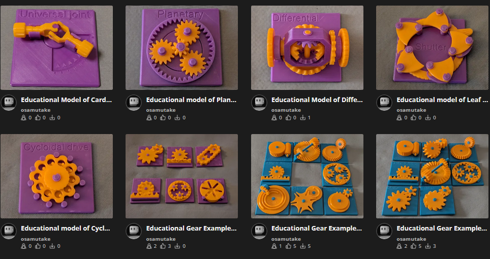
The present set
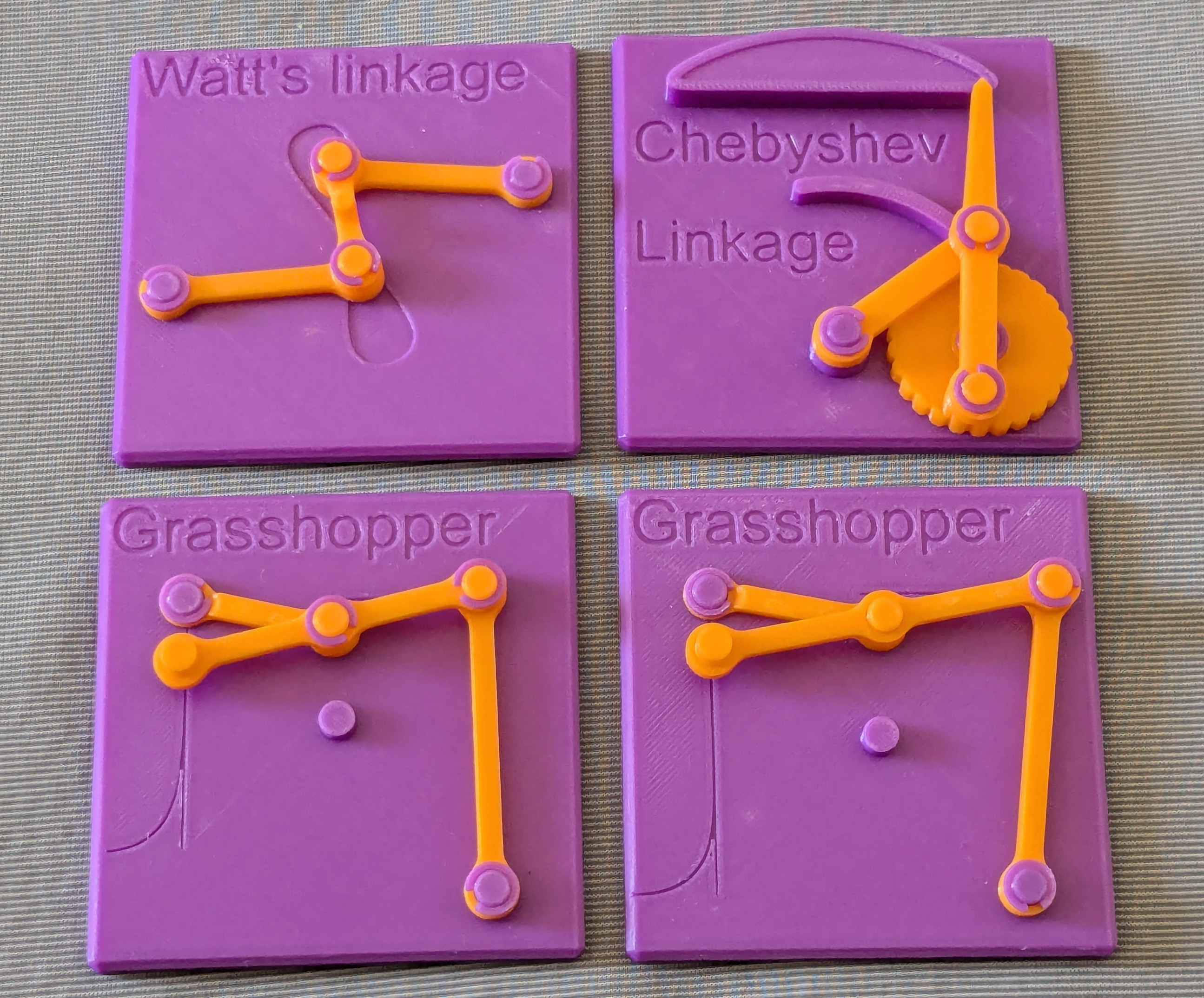
This set contains educational models of four-bar linkages that realize approximate straight-line motions.
- Chebyshev lambda linkage
- Watt's Linkage
- Grasshopper Linkage (two types)
By using such mechanisms, the motion of a coupler point can be constrained to an approximately straight-line path using only rigid links connected by revolute joints, without any linear guide or prismatic pair.
Brief Description
Watt's Linkage
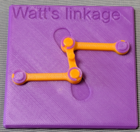
Watt's linkage was devised by James Watt, renowned for his pioneering work on the steam engine. Two long links of equal length connect the ends of a shorter central link to two fixed pivot points on the base plate. When viewed as a four-bar linkage, the imaginary line connecting the two fixed pivots serves as the fourth link. The fixed pivots are positioned such that their horizontal separation equals approximately twice the length of the long links and their vertical separation equals the length of the short link — geometry that places the mechanism in a nominally parallel configuration, with the short link perpendicular to both long links. In practice, the mechanism is often set slightly off this position to optimize the straightness of the output motion. The coupler point is located at the midpoint of the short central link. This point traces a distorted figure-eight path on the base plate, the approximately straight portion of which is what allows the mechanism to function as an approximate straight-line mechanism.
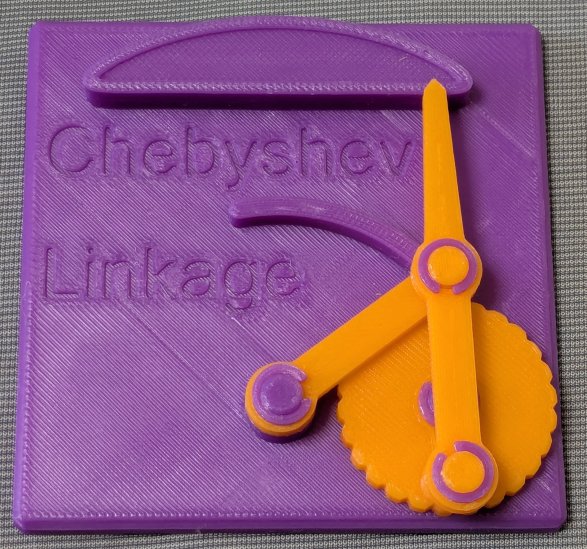
Chebyshev Lambda Linkage
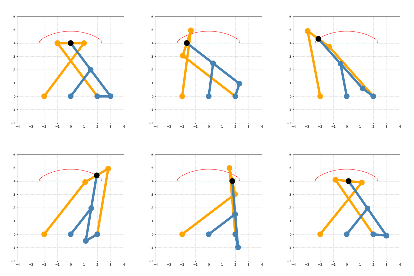
The Chebyshev linkage is one of the earliest known approximate straight-line mechanisms, devised by Russian mathematician Pafnuty Chebyshev, who sought to improve upon earlier straight-line mechanisms such as Watt's linkage. It consists, as shown in orange in the figure below, of a short link of length 2a connected at both ends to two long links of length 5a, which in turn connect to fixed pivots on the base plate. The midpoint of the short link serves as the coupler point. The Chebyshev Lambda Linkage achieves the same motion through a different configuration, as shown in blue in the figure below.
In the lambda variant, three links of lengths 5a, 2.5a, and a are used. The 2.5a link connects to the midpoint of the 5a link, and the a link connects to one end of the 5a link; the free ends of both shorter links attach to fixed pivots on the base plate. The 5a link and the 2.5a link extending from its midpoint resemble the Greek lowercase letter λ, giving this variant its name. The two fixed pivots are separated by a distance of 2a, and the pivot of the 2.5a link lies at the midpoint between the two fixed pivots of the corresponding standard Chebyshev linkage. In this configuration, the 5a and a links are parallel to their counterparts in the standard linkage, and the free end of the 5a link coincides with the coupler point. In this model, the a link is replaced by a disk for ease of manipulation.
The coupler point traces a path similar to that of the Theo Jansen mechanism. However, unlike the Theo Jansen mechanism, the trajectory is traced above the mechanism, making it unsuitable for walking on a surface. Instead, it lends itself to suspended locomotion, where the mechanism travels along an overhead track.
Grasshopper Linkage
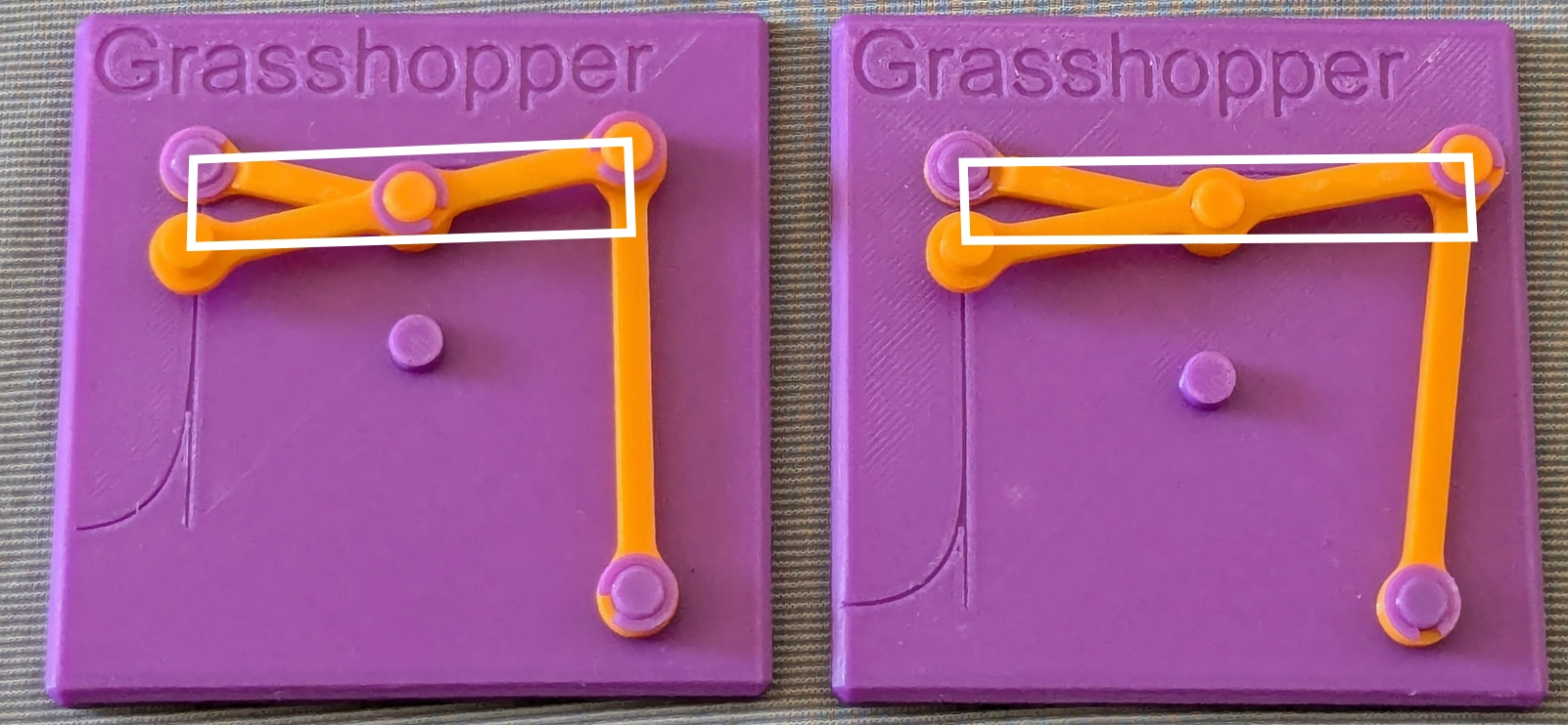
The Grasshopper linkage is based on a configuration in which one end of a link of length a is connected to the midpoint of a link of length 2a. In this model, the other end of the a link is fixed to the upper left of the base plate. The geometry becomes clear by imagining a rectangle whose three corners are the fixed point and the two ends of the 2a link, with its sides running horizontally and vertically. In this rectangle, the 2a link forms one diagonal, and the a link forms half of the other. It follows that when the right end of the 2a link moves horizontally along the same height as the fixed point, the left end — which serves as the coupler point — travels along a vertical straight line passing through the fixed point.
This would be perfect straight-line motion, but in the Grasshopper linkage the right end of the 2a link is constrained to move along an arc rather than a straight line, by a third link whose lower end is fixed to the base plate. The longer this third link, the closer its arc approximates a straight line, so longer is better — though there is no single optimal length. Any deviation of the arc from a straight line causes a corresponding deviation of the coupler point from its ideal vertical path. The base plate is engraved with both the ideal straight line and the actual coupler point trajectory, allowing the difference to be seen directly.
This set includes two variants of the Grasshopper linkage. In the left model, the third link is vertical in the nominal configuration, giving better approximation for small displacements. In the right model, the third link is tilted slightly to the right, trading some accuracy near the center for a wider range of near-linear motion. Moving the coupler point by hand allows the difference between the two variants to be felt directly.
Related Models
Case
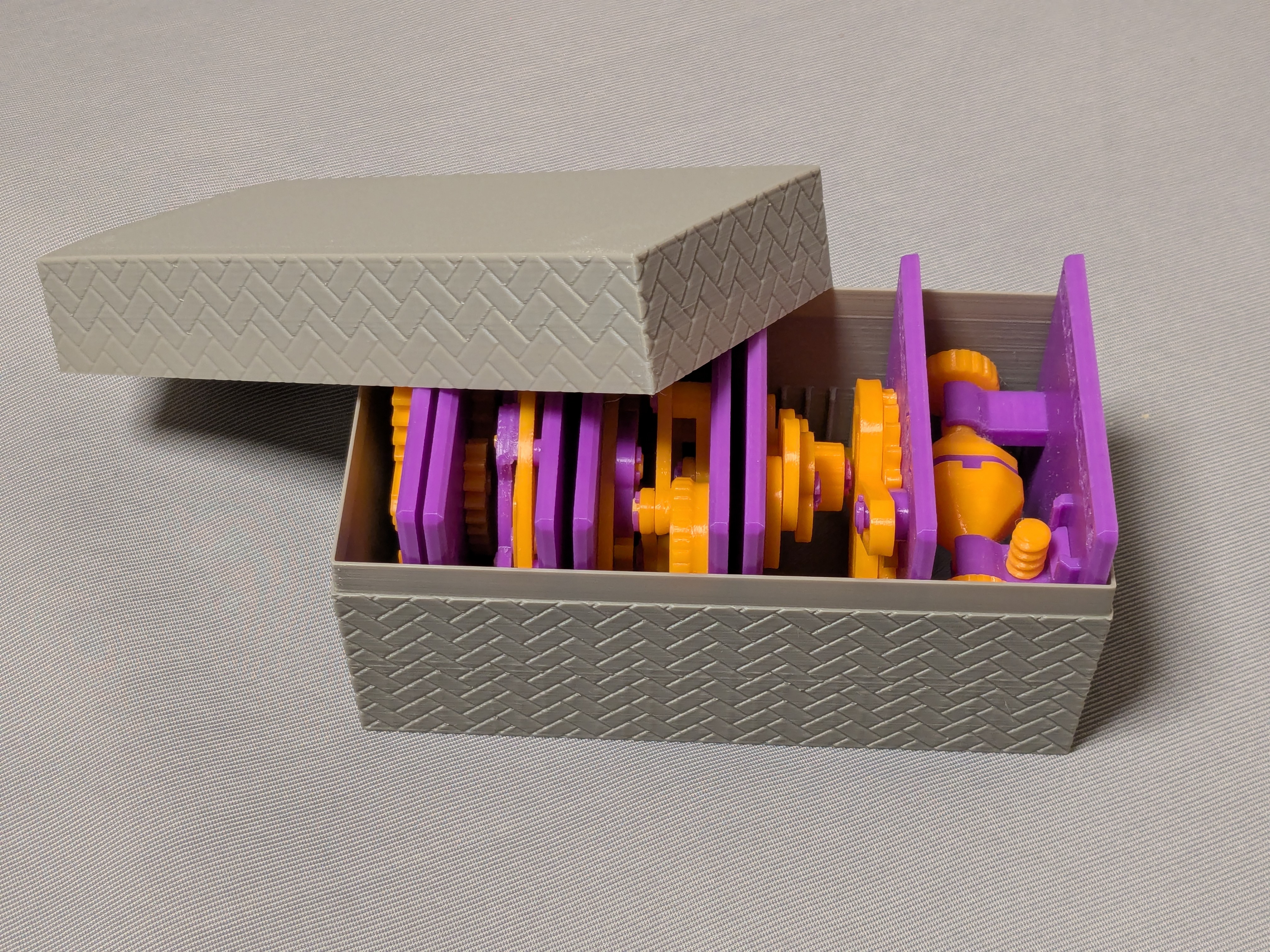
This model is compatible with the case included in my first set.
Printing
- Use the models named ???-printable.stl for printing.
The models named ???-assembled.stl are provided just to show how they should be assembled.
- Use well-dried PETG to have better dimensional accuracy.
- Use 0.1 mm or 0.08 mm layer height to have smoother surfaces.
- Use slow printing speed for overhangs.
- Select “Random” seam position to have smoother rotation.
Randomly distributed seam should be easily worn out after some wearing.Printing
Sanding and Filing
Note that, in this model, the rotation of the bases for bearings is intentionally made not too smooth.
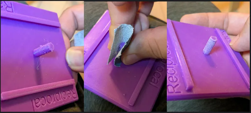
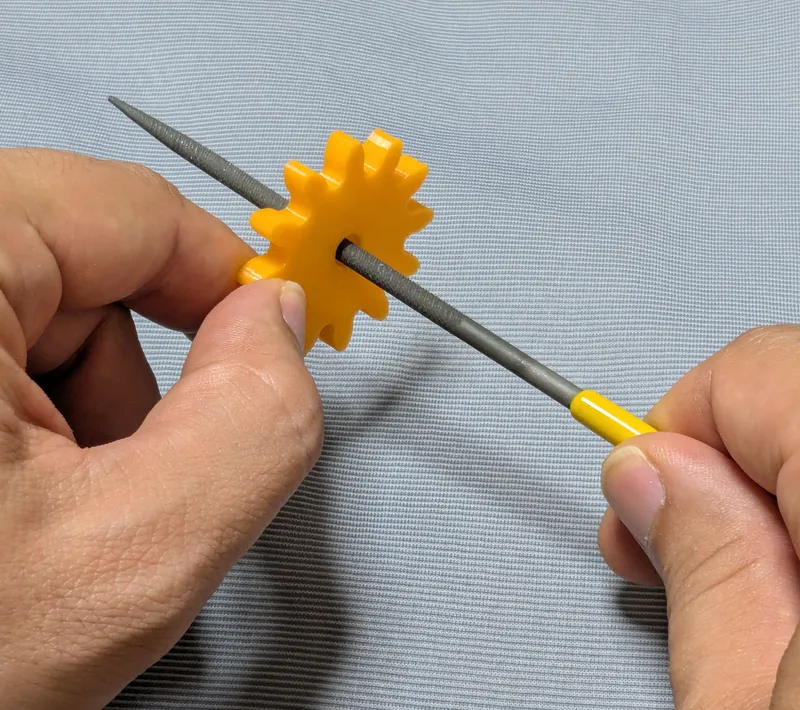
Sometimes, the gears suffer from the stringing effect and/or elephant foot effect, resulting in a too tight fit to the shafts (they are designed with a 0.15 mm radial clearance).
If you see rough surface on the shafts due to stringing, sand off the roughness with a small piece of sand paper.
If you feel the gears do not rotate smoothly due to an elephant effect, widen the hole slightly by using a thin round bar file.
Without those issues, the parts should rotate very smoothly with minimal friction.
Assembly
Just secure the parts by the retaining rings.
Other examples
You may also be interested in the models in my educational mechanical mechanism examples.
Find them in this collection:
https://makerworld.com/collections/15048577-my-educational-mechanism-models
Happy printing!
Acknowledgement
I got into gears thanks to K.$uzuki's amazing articles and YouTube videos. Many of the mechanisms shown in this series came from the introductions on his website. He also makes excellent gear models himself. This series wouldn’t have existed without his inspiration.
I learned a lot about technical detail of designing gear tooth profiles from Haguruma-No-Hanashi website. I’m truly grateful for that.
License (2026-03-13 updated)
- The 3D model(s) are licensed under Creative Commons Attribution 4.0 International. (unchanged)
- However, the text and images on this page are copyright reserved. (added on 2026-03-13)
Design by osamutake on MakerWorld (license: BY).